An Ethernet VirtuaLAB provides a software-controlled environment for generating, transmitting, and analyzing Ethernet packets to test Ethernet SoCs mapped inside an emulation platform.
Source: Electronic Design
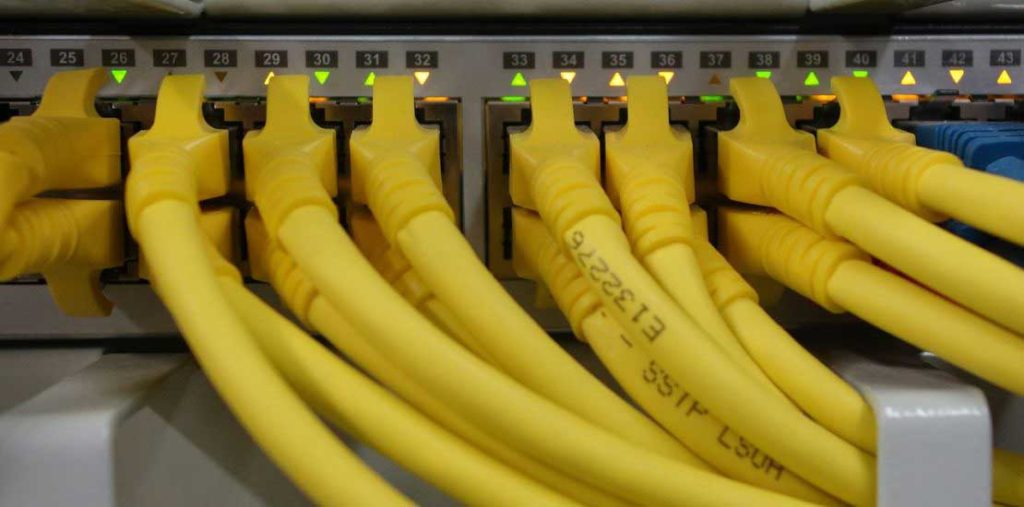
With the spectacular surge in demand for connectivity, the Internet has become a major communications highway for billions of users. According to “Internet Live Stats,” the Internet reached out to three billion people in 2014. That’s about 40% of the world population.
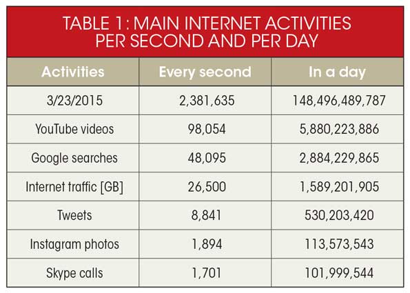
Loosely defined as a “worldwide system of interconnected networks and computers,” it enables a broad range of data-communications services, such as email, video downloads, Google searches, tweets, Skype calls, and many more. Table 1 lists the main Internet activities per second and per day.
The origin of the Internet can be traced to the convergence of multiple inventions at a variety of places and at different points in time, championed by a multitude of players. Vertical developments include packet-switching technology, the communication protocols, and telecom-industry activities since the 1960s. Xerox Palo Alto laboratories created the Ethernet standard developed for “local-area networks” (LANs) based on the TransmissionControl Protocol –– Internet Protocol (or TCP/IP). For other related terms, see the Glossary at the end of the article.
The invention that propelled the Internet to reach three-billion people, and to make it the network that it is today, was the personal computer. Without personal computers and their associated equipment, such as printers and scanners, the Internet would have been confined to the military and academic institutions.
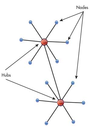
In network verbiage, all of the devices connected to a network are classified as network nodes. In the most basic type of network, nodes connect together via hubs. That is, a multiport device copies any arriving pack of information to all other ports (nodes) connected to it (Fig. 1).
The problem with this simplistic approach is that it thwarts the growth of the network beyond a few devices or nodes. Four issues prevent network expansion based on hubs:
• Bandwidth: Measured by how much data can be transferred in a set amount of time. In a hub network, users share the total bandwidth.
• Latency: Measured by the time a packet reaches its destination. In a hub network, the transmission ruling increases the latency beyond the acceptable.
• Network failure: In a hub network, a node can create problems for other nodes, such as excessive broadcast or improper speed settings.
• Collision: When nodes transmit packets at the same time, a collision occurs, and retransmission becomes necessary.
To address and correct these issues, the industry developed new devices in place of hubs. Among them, switches and routers preserve bandwidth, lower latency, avoid network failures, and avert collisions.
An Ethernet SoC Case Study
Long gone are the days when Kalpana introduced a seven-port Ethernet switch handling 10-Mb/s throughput in 1989. Today, Ethernet switches and routers reach 256 ports, and by year’s end, 1024 ports. They also can handle throughputs of 1/10/40/100/120 Gb/s. While the industry can foresee the growth in number of ports in the future, less obvious is the increase of bandwidth to 1000 Gb/s, due to limits in the transmission medium. We could see a move to adopt parallelism to expand the bandwidth. Latency in networking switches has constantly decreased, and today, the lowest latencies drop below 1 µs.
A larger number of ports, expanding throughput, decreasing latency, and overall improvement in security and ease of use make today’s network switches and routers among the largest IC designs ever developed, reaching beyond a half billion gates. Only the largest processor and graphics chips are bigger.
Verification of such complex IC designs before silicon availability is a daunting task. Let’s consider the design of a modern system-on-chip (SoC) with a 128-port Ethernet interface, and a variable bandwidth of 1/10/40/100/120 Gb/s.
While hardware-description-language (HDL) simulation can be used at the block level, verifying the entire design of several hundred million gates with simulated traffic is unrealistic, and must be ruled out. This is a primary case for using hardware emulation in in-circuit-emulation (ICE) mode.
What’s unique to this verification mode is the ability to test a design with real traffic. The setting would require one Ethernet tester per port. Since a direct connection is not possible due to rather different speed domains between tester and emulated design under test (DUT), a speed rate adapter is inserted between the two. This reconciles the tester’s fast speed to the relatively low speed of the emulated DUT.
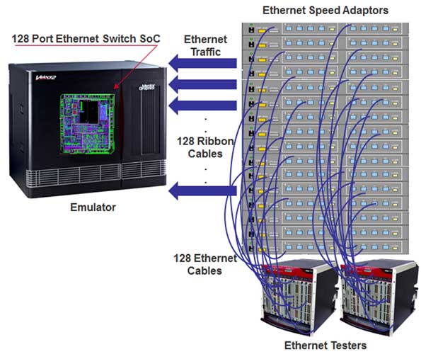
The design in the analysis includes 128 ports, which leads to a setup with 128 Ethernet testers and 128 Ethernet speed adapters with lots of cables (Fig. 2). Apart from the spaghetti-cable arrangement, the potential unreliability of the hardware, and the overall cost, what’s most disappointing is that the entire setup would only support a single user located in the proximity of the emulation lab.
VirtuaLAB for Networking Design Verification
Let’s compare this to an equivalent setup using a virtual approach like the Ethernet VirtuaLAB from Mentor Graphics. In this scenario, the Ethernet testers are modeled in software running under Linux on a workstation connected to the emulator. The model is an accurate representation of the actual physical tester, based on proven implementation intellectual property (IP).
This virtual tester includes an Ethernet Packet Generator and Monitor (EPGM) that generates, transmits, and monitors Ethernet packets with the DUT. It has the ability to configure GMII, XGMII, XLGMII/CGMII, and CXGMII interfaces for 1G, 10G, 40G/100G, and 120G respectively. The VirtuaLAB software also performs off-line analysis of the traffic, provides statistics, and supports several other fuctions listed below.
The interface between the VirtuaLAB virtual tester and the DUT consists of one instance of VirtuaLAB-DPI communicating to a Virtual Ethernet xRTL (extended register transfer level) transactor hooked up to a Null-PHY, connected to the DUT. One xRTL transactor is required for each port of any xMII-supported type (Fig. 3).
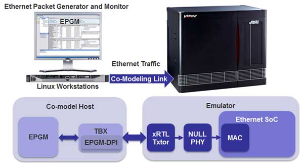
The VirtuaLAB provides up to 32 GMII, XGMII, XLGMII/CGMII, and CXGMII ports per workstation. Multiple VirtuaLAB applications can be bundled together across multiple workstations––known as a multi-co-model––to support large port count configurations. High Speed Link (HSL) cards are used to connect Co-model channels from workstations to the emulator. This tightly integrated transport mechanism is under the hood, tuned for maximum wall clock performance, and is transparent to the testbench. Data-plane emulation throughput scales linearly with the port count because of this parallel runtime and debug architecture. Figure 4 provides a high-level view of the multi-co-model topology.
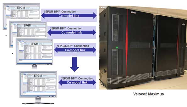
Apart from enabling high data-plane transport, several other benefits can be derived when using this approach. First, reconfiguring the virtual tester to perform various functions, as listed below, is fast via remote access. Second, the workstation is a stable and reliable piece of equipment acquired at a fraction of the cost of a complex Ethernet tester of equivalent functionality.
Even more important is the ability to support multi-concurrent users, essential in backing up a large software-development team. Last, but not least, a VirtuaLAB setup is an ideal solution for setting up an emulation datacenter as an enterprise-wide emulation resource, using Enterprise Server’s IT management capabilities.
The Virtual Ethernet Device (VirtuaLAB) supports a Directed Test mode operation to define and control the streaming of specific packets to the emulated DUT, as well as trace the packets returned from the DUT. It can be configured for multiple co-model hosts supported by one instance of software running on up to eight co-model hosts, and a Virtual Ethernet xRTL Transactor connected to Null-PHY as well as to the DUT on the emulator.
VirtuaLAB instances can be managed through a centralized “Controller” software application invoked from one of the workstations.
Complex Testing
The Ethernet VirtuaLAB is well-suited for complex test-scenario generation and monitoring. An interactive and batch-mode TCL command interface is used to control all MACs and generate a myriad of protocols and traffic flows. Examples of Ethernet packet construction includes non-homogenous packet types, all Ethernet frame types, raw payload, Jumbo packets, VLAN, TCP/IP, UDP, PAUSE frames, IGMP, ARP, etc. Percentages of traffic per protocol type can be mixed with differing packet sizes or random size per flow. Packet-transmission arbitration includes multiple algorithms, such as WRR, DWRR, SO, and Random.
The Ethernet VirtuaLAB supports stress testing and error injection for complex switching topology using the dynamic port-group reconfiguration feature for 1/10/40/100-Gb/s full-duplex speeds. For example, xMII/PCS widths, link speeds, link up/down, and fault states can all be dynamically configured during emulation runtime, and need no recompile steps to support testing numerous port-group configurations. Protocol and performance violations like CRC, Preamble, IFG, and line rate are reported. Packets can be reviewed in interactive or batch sessions to examine packet statistics, Tx/Rx trace, metadata (e.g., signatures), time stamps, and all content on the wire.
Complex Analysis
One of the hallmarks of emulation is its ability to do complex performance analysis of large and deep state-full systems. Emulation is used to validate packet classification, filtering, rates, BW, policing, traffic shaping, CoS, sequence drop, and IFG analysis per flow using signature analysis.
In some cases, millions of packets may be needed to hit steady-state analysis points of interest in the design. Take, for example, measuring bit rates for traffic flows in a terabyte Ethernet switch. Virtual Ethernet signature generation and packet time stamps (TS) are used to calculate these measurements.
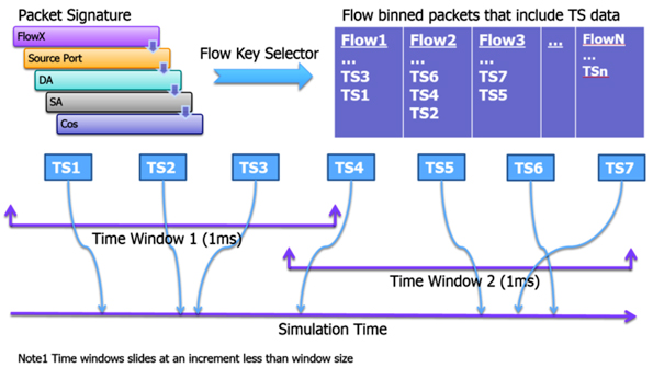
In the measurement example (Fig. 5), Rate FlowX = (Bytes In WindowFlowX) * 8 / (1-ms Time WindowFlowX). Measurements such as these per port per flow can easily consume a week to extract in simulation for large port-count devices. In emulation, these same measurements can be performed within an hour.
Summary
In summary, an Ethernet VirtuaLAB provides a software-controlled environment for generating, transmitting, and analyzing Ethernet packets to test Ethernet SoCs mapped inside an emulation platform. With simulation, you can typically verify 1000 packets per day, whereas emulation and VirtuaLAB Ethernet can handle over 11 million per day. Multiple concurrent users located anywhere in the world can benefit simultaneously. A fast, accurate, easy-to-use solution, VirtuaLAB brings complex Ethernet SoC designs to market on schedule for increased productivity.
Glossary
ARP: Address Resolution Protocol
BW: bandwidth
CoS: class-of-service
CRC: cyclic redundancy check
DA: destination address
DPI: direct programming interface
DUT: device under test
DWRR: distributed weighted round robin
EPGM: Ethernet Packet Generator and Monitor
Gb/s: gigabits per second
HDL: hardware description language
HSL: high-speed link
ICE: in-circuit-emulation
IFG: inter-frame gap
IGMP: Internet Control Message Protocol
IP: Internet Protocol //intellectual property
LAN: local-area networks
MAC: media access controller
Mb/s: megabits per second
PCS: physical convergence sub-layer
PHY: Ethernet physical transceiver
SA: source address
SO: strict order
SoC: system-on-a-chip
TCL: tool control language
TCP: Transmission Control Protocol
TS: time stamp
Tx/Rx – transmit/receive
UDP: User Datagram Protocol
VLAN : virtual local-area-network protocol
WRR: weighted round robin
xMII: media independent interface
xRTL: extended register transfer language